A Highly Practical Guide to Digital Twins Through the International Standard ISO 23247
A practical guide to ISO 23247 for manufacturing digital twins. Learn the definition, architecture, OME data models, network design, digital thread and twin composition, plus a NIST five-axis CNC implementation and lessons from real-world research.


On this page
- The Decisive Difference Between “Just Displaying Data” and a “True Digital Twin”
- Digital Shadow vs. Digital Twin, Explained with Google Maps
- Overview of ISO 23247: The Parts That Make Up a Digital Twin
- ISO 23247-1: Overview and General Principles
- ISO 23247-2: Reference Architecture
- ISO 23247-3: Digital Representation
- ISO 23247-4: Information Exchange
- Two New Standards Added in 2026
- ISO 23247-5: Digital Thread for Digital Twin
- ISO 23247-6: Digital Twin Composition
- The Four Major Architectural Entities and Their Functional Mapping
- 1. User Entity
- 2. Digital Twin Entity / Core Entity
- 3. Device Communication Entity / DCDCE
- 4. Observable Manufacturing Elements (OME) / Physical Layer
- The Day a Factory Standard Like ISO 23247 Could Transform Office Work: The Boundary with Existing BI and CRM
- Existing BI and CRM as One-Way Digital Shadows
- Bidirectional Autonomous Control Applying the ISO 23247 Design Philosophy
- Recommended Data and Network Design: Bridging to Professional Implementations
- Standard Mapping of Information Attributes
- Four Network Topologies and the Recommendation of MQTT
- User Network
- Service Network
- Access Network
- Proximity Network
- Advanced Practical Example: How NIST Built a Digital Twin of a Five-Axis CNC Machine Tool
- 1. First Challenge: Capturing the Machine’s Raw Voice
- 2. Second Challenge: The Interface Barrier and Co-Simulation
- 3. Final Result: Detecting a Hidden Difference During a One-Hour Machining Process
- Advanced Use Cases in High-Tech Manufacturing
- Four Robots Coordinating to Assemble an Aircraft Wing
- From Sweden to New York: “15% Cost Reduction” in F-35 Production
- Beyond the Limits of G-Code: STEP-NC (AP238) and the Future of the Digital Thread
- The Harsh Gap Between the Ideal and Reality of Digital Twins Revealed by Academic Research
- Statistical Table: The “Ideal vs. Reality” Gap in ISO 23247-Aligned Digital Twins
- Gap 1: More Than 80% Are Effectively Digital Shadows Rather Than Fully Closed-Loop Twins
- Gap 2: Several Advanced Functional Elements Had an Implementation Rate of 0%
- Gap 3: The Function Most Needed in Practice Is Not Explicitly Defined as a Core Component
- Gap 4: The Hidden Quagmire of Ad Hoc Security and Access-Control Implementation
- Three Practical Lessons for Designing Digital Twins
- 1. Start One Step at a Time from a Digital Shadow
- 2. Build Data Storage and Version Management from the Beginning Even If the Standard Does Not Explicitly Define Them as Dedicated FEs
- 3. Take Full Advantage of Technology Neutrality
- References: URLs, Papers, and Technical Resources
- 1. Standards and Official Sources
- 2. Technical Guides and Case Studies
- 3. Key Academic Papers and DOI Links
- 4. Major Cloud and Digital Twin Development Platforms Mentioned in This Article
“Wouldn’t it be great if something could automatically water the basil and lettuce on my balcony while I’m away for a few days?”
“I wish I had a smart planter that could adjust the brightness of its LED light automatically according to the amount of sunlight.”
Have you ever thought something like this?
In fact, this is one of the most familiar examples of the Digital Twin, one of the hottest trends in manufacturing and the IT industry around the world today.
However, when you actually try to build a digital twin—from a seemingly simple home automated growing system to a production line for an F-35 fighter aircraft made up of tens of thousands of highly precise parts—you quickly run into a major challenge: How do you make multiple sensors, lights, pumps, and AI systems work together without interfering with one another?
The ISO 23247 series, an international standard for digital twins, was created to address this challenge.
In this article, we explain this seemingly complex international standard in an intuitive and easy-to-understand way. In the second half, we also dive into more advanced technical detail, including a full-scale implementation example using a five-axis CNC machine tool at the U.S. National Institute of Standards and Technology (NIST), as well as the gap between the ideal and reality of digital-twin implementation revealed by recent research.
The Decisive Difference Between “Just Displaying Data” and a “True Digital Twin”
First, what exactly is a digital twin? ISO 23247-1 defines it as follows:
A digital twin is a “fit-for-purpose digital representation” of an observable manufacturing element (OME), with “synchronisation” between the physical object and its digital representation.
Let us apply this concept to a familiar example.
Digital Shadow vs. Digital Twin, Explained with Google Maps
Many systems commonly described as “digital twins” in general news coverage are, in practice, closer to what is often called a digital shadow—a one-way reflection.
Digital shadow = ordinary car navigation system that only displays information
It shows road congestion data from the physical world on a screen, but the navigation display does not automatically turn the steering wheel to avoid traffic. Data flows in only one direction: physical → digital.
Digital twin = smart navigation integrated with fully autonomous driving
When the navigation system detects congestion, it communicates bidirectionally with the vehicle computer and automatically steers the vehicle onto an optimal route. Data circulates as physical → digital → physical.
In the smart-planter example, a system that merely displays “soil moisture is decreasing” as a graph on your smartphone would be a digital shadow.
By contrast, a digital model that detects the decline in soil moisture, calculates the optimal amount of water based on the plant’s current growth stage and the day’s weather forecast, and then sends a command back to the physical planter’s pump—“give 50 ml of water”—is a true digital twin in this article’s framing.
Overview of ISO 23247: The Parts That Make Up a Digital Twin
The ISO 23247 series defines rules for constructing this kind of bidirectional system safely and reliably, even in environments where equipment from many different manufacturers must coexist. As of 2026, the series consists of six parts.
ISO 23247-1: Overview and General Principles
Overview and general principles
This part defines terminology such as what a digital twin is and specifies the basic requirements for the overall system. It establishes the conceptual framework and overall policy for properly linking manufacturing elements in the physical world with the digital space in order to achieve goals such as quality improvement and predictive maintenance.
ISO 23247-2: Reference Architecture
Reference architecture
This part defines the functional structure used when designing and building a digital-twin system, including four major entities or layers: the user, service/core functions, digital twin, and device/physical side. By standardizing the roles and boundaries of each function, it becomes easier to connect simulators and analysis tools from different vendors.
ISO 23247-3: Digital Representation
Digital representation of manufacturing elements
This part defines rules for describing information so that people, machines, materials, environments, and other target elements can be represented accurately in digital space. It structures and stores both static data, such as model numbers and CAD geometry, and dynamic real-time data, such as axis coordinates and spindle speed, in a unified format.
ISO 23247-4: Information Exchange
Information exchange technologies
This part defines approaches for exchanging data securely and with low latency between layers and external systems, including communication protocols such as MTConnect, MQTT, and OPC UA, as well as network configurations. It provides guidance for building secure data pipelines according to factory security and response-time requirements.
Two New Standards Added in 2026
ISO 23247-5: Digital Thread for Digital Twin
Digital thread
This part specifies how to connect information from different stages of manufacturing—such as product design, manufacturing processes, equipment status, and inspection results—into one continuous digital thread.
When a quality issue occurs, this makes it possible to trace and analyze related information all the way from design data to machining conditions during production, equipment history, and inspection data.
ISO 23247-6: Digital Twin Composition
Digital twin composition
The latest standard, ISO 23247-6, which was formally issued on July 28, 2026, defines three approaches for “composition” that connect separate digital twins, including twins developed by third parties or different vendors.
- Integrated: Boundaries between individual twins are effectively removed, and the twins are tightly coupled as one large system.
- Unified: Twins from different vendors connect through common APIs and data formats using a common interface.
- Federated: Each twin retains its own independence and sovereignty while exchanging information when necessary, much like a loose alliance. This approach is useful for inter-company collaboration and very large distributed networks.
The Four Major Architectural Entities and Their Functional Mapping
ISO 23247-2 organizes a complex digital-twin system into four major entities. Let us walk through them from top to bottom using the smart planter as an example.
1. User Entity
This is the application or dashboard directly seen by the person growing the plant.
Example
The smartphone screen displays information such as “The lettuce is growing well” and “Current room temperature: 24°C,” and provides buttons for actions such as “Water manually” when necessary.
2. Digital Twin Entity / Core Entity
This is the “brain” of the overall system.
Example
Based on data coming from the physical layer, it simulates factors such as the plant’s current photosynthesis rate and predicted soil drying in digital space, then determines an optimal adjustment plan.
3. Device Communication Entity / DCDCE
This acts like the “nervous system” connecting field electronics with the digital twin.
Example
It reads raw data such as “soil moisture: 20%” from temperature, humidity, and illuminance sensors. It also receives instructions from the twin, switches on the pump, and physically dispenses water.
4. Observable Manufacturing Elements (OME) / Physical Layer
These are the real-world elements that the digital twin is intended to represent. The ISO framework classifies manufacturing elements into categories. Using the smart-planter example, they can be mapped as follows.
- Personnel: You, the person growing the plants, and workers who support seeding and harvesting.
- Equipment: LED lights, water pumps, soil-moisture sensors, cooling fans, and other operating machinery.
- Material: Soil, liquid fertilizer, irrigation water, and other raw materials consumed during the growing process.
- Process: Photosynthesis, seeding, fertilization, automatic watering, and other cultivation activities and procedures.
- Facility: The greenhouse or room where the planter is installed, including power, water, and structural infrastructure.
- Environment: Room temperature, humidity, carbon-dioxide concentration, ambient sunlight, and other surrounding environmental conditions.
- Product: The final harvested output, such as healthy lettuce or basil.
- Supporting documents: Variety-specific growing manuals and guidelines for configuring watering schedules.
The Day a Factory Standard Like ISO 23247 Could Transform Office Work: The Boundary with Existing BI and CRM
When people encounter the idea in this standard that a process itself can also be represented as a twin, some may think:
“Ultimately, couldn’t we visualize business progress in an office rather than a factory? We could collect internal email histories, identify who is accumulating delayed customer replies, analyze how that affects customer acquisition, and predict near-term delay risks.”
That intuition is understandable. But another question immediately follows:
“Isn’t that something BI and CRM tools have already been doing for years, just without calling it a digital twin?”
This is one of the most important and interesting boundaries to examine when trying to understand the essence of digital twins.
Existing BI and CRM as One-Way Digital Shadows
A system that statistically analyzes email response delays and their impact on customer acquisition can already be implemented within conventional BI or CRM frameworks.
At this stage, however, data flows only one way:
Physical world, such as employees’ email activity → digital world, such as dashboards and reports
What happens when a problem occurs?
The system may display a report saying, “Last month, customer acquisition fell by 15% because Person A’s responses were delayed.” A human manager or the employee then has to interpret the report and consciously change behavior: “Let’s respond faster this month.”
Because the system is merely reflecting or visualizing information, under the ISO 23247 definition presented in this article it still remains a one-way digital shadow, or simply data representation and reporting.
Bidirectional Autonomous Control Applying the ISO 23247 Design Philosophy
Once this system is equipped with the bidirectional synchronization and device control specified by ISO 23247-2, it evolves into a “true digital twin” that autonomously operates the business process itself in real time.
Real-Time Prediction
The system synchronizes current email-exchange data with information about Person A’s current workload and schedule. The moment an important customer sends a new message, the twin-side simulation may predict:
“Given Person A’s current workload and historical statistics, the message is unlikely to be answered within three hours, which may reduce the probability of winning the order by 35%.”
In other words, it predicts a future operational problem in real time.
Autonomous Feedback, Control, and Actuation
Before a human notices, the system itself sends a control command back to the office system to avoid the problem.
Automatic task rerouting / autonomous workload distribution
The system automatically transfers handling responsibility for Person A’s email to Person B, who currently has available capacity, and displays an urgent message on Person B’s screen asking them to reply on Person A’s behalf.
Dynamic slack allocation
Based on delay predictions, if the twin determines that a reply will not be sent within two hours, it autonomously instructs the email system to send an acknowledgment message to the customer. This helps prevent dissatisfaction while dynamically creating a scheduling buffer for the full response. Intelligent alerts about whether such a buffer is needed, and measurement of how those buffers affect conversion rates, represent the kind of closed-loop optimization this article associates with digital twins.
Bottleneck removal / context adjustment
The system automatically moves the deadlines for Person A’s lower-priority tasks, such as an internal daily report, to the next day, reducing their cognitive load in real time.
The distinction is therefore whether humans simply look at data and decide what to do, as in conventional BI and CRM, or whether the system itself feeds decisions back into the operational process in real time to avoid and repair bottlenecks autonomously.
This is the cold, decisive boundary separating a simple aggregation tool from a “true digital twin.” The design philosophy of the rigorous ISO 23247 international standard provides a powerful foundation for safely and reliably constructing this kind of bidirectional autonomous system—even for office work.
Recommended Data and Network Design: Bridging to Professional Implementations
Now let us move from the basics of the smart planter to the design specifications used in large-scale smart factories.
Standard Mapping of Information Attributes
ISO 23247-3 defines basic information attributes for modeling physical manufacturing elements. When implementing these as actual data structures, the standard and its annexes point to related industrial standards and technologies.
Among these attributes, the identifier is treated as mandatory in the article’s source material.
| Information Attribute | Smart Planter Example | Standards / Technologies Used in Factory Systems |
|---|---|---|
| Identifier | Unique ID of a device or plant pod | UUID, URL, URI, AAS, etc. |
| Characteristics | Maximum LED wattage, pump flow rate | IEC 62264-2, eCl@ss, ISO 13584-42 |
| Schedule | LED lighting plan, e.g. 12 hours per day | ISO 8601, production process calendars |
| Status | Running, low-water warning, abnormal state | VDMA 24582 |
| Location | Indoor position, e.g. near a window or second shelf | GPS, address, ISO 6709 |
| Report | Records such as watering history | QIF, MTConnect |
| Relationships | Positional relationship between sensor and pod | Topology-management standards, AAS relationship definitions |
Four Network Topologies and the Recommendation of MQTT
ISO 23247-4 clearly defines network connections used to design communication within the system.
User Network
This connects the user interface and the digital twin. Familiar web technology REST (HTTP/HTTPS) is specified as the standard protocol.
Service Network
This connects internal servers that make up the digital twin. If the entire system runs inside a single computer, a physical network may not be necessary.
Access Network
This is the most important route connecting field data-collection and control devices to the digital-twin core. The standard explicitly states that when the same sensor data is monitored simultaneously by multiple systems, a publish/subscribe model such as MQTT is strongly recommended to avoid communication conflicts.
Proximity Network
This is the local network connecting sensors or machines with a control board. If the control controller is physically built into the machine itself, this network may be omitted.
Advanced Practical Example: How NIST Built a Digital Twin of a Five-Axis CNC Machine Tool
Now let us see how the “four major entities” and the “MQTT access network” learned through the smart-planter example scale up to a professional, highly advanced manufacturing environment.
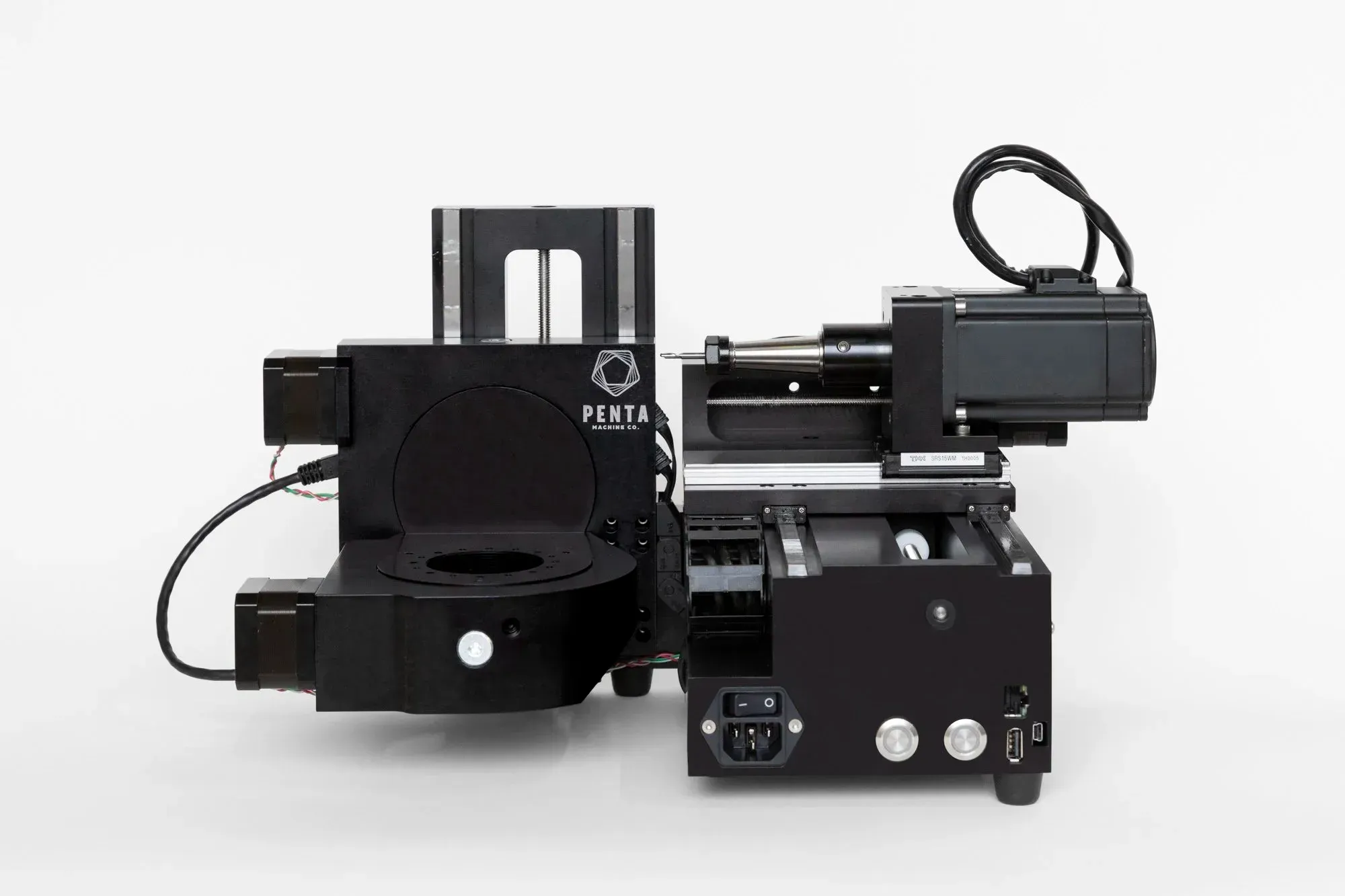
The U.S. National Institute of Standards and Technology (NIST) built and demonstrated an ISO 23247-based real-time data pipeline for a Pocket NC V2-10, an advanced five-axis desktop milling machine.
Even an institution such as NIST did not begin by trying to achieve perfect autonomous control from day one. Instead, it first focused on constructing a high-precision monitoring twin that reproduced the behavior of the real machine—its five-axis motion—in real time and detected small discrepancies between the physical machine and its digital counterpart.
1. First Challenge: Capturing the Machine’s Raw Voice
Pocket NC is a highly precise and complex five-axis machine tool with XYZ linear motion plus two rotary axes.
The first step in creating its digital twin was to capture raw physical data describing where the machine was positioned and how fast it was rotating, with as little delay as possible.
The NIST team introduced a custom Python adapter into the machine controller to extract the current positions of all five axes, spindle speed, and G-code execution status.
The raw data was converted on the spot into SHDR format, a lightweight data stream used with MTConnect, and then streamed through socket communication to an aggregation engine—a C++ MTConnect agent running on a Linux host PC.
2. Second Challenge: The Interface Barrier and Co-Simulation
The team then tried to feed the collected data into a 3D CAD model so that it would simulate the real machine’s motion accurately.
At this point, however, they encountered a major specification limitation. The core engine of the physical simulation software, Altair Inspire Motion, did not provide a direct interface for receiving real-time streaming data from an external source.
The team overcame this constraint by inserting an intermediate simulator, Twin Activate, as a bridge and using the IoT protocol MQTT through Mosquitto to create a co-simulation pipeline.
A Python script published data through MQTT; Twin Activate received it immediately, converted it into internal simulation signals, and passed it into the simulator.
This chain made it possible to overcome the software-interface limitation and reproduce the motion of a 3D model synchronized with the physical machine.
3. Final Result: Detecting a Hidden Difference During a One-Hour Machining Process
Data from the completed real-time pipeline was ultimately visualized on a monitoring interface using the analytics tool Panopticon, with a web server based on Apache Tomcat.
The machining operation lasted a total of 3,734 seconds, or roughly one hour.
During the complex five-axis machining process, graphs overlaid the commanded position generated by the physical machine and the reproduced position calculated by the digital twin.
The digital twin revealed a key discrepancy: during transitions where the cutting direction changed or an axis rotated rapidly, visible position error appeared between the physical machine and the values represented digitally.
This small gap between ideal simulated motion and the behavior of the actual machine is exactly the kind of discrepancy that a digital twin can make visible in real time.
By capturing such otherwise invisible errors, the experiment opened the door to future work in automatic machining-accuracy compensation and machine-life prediction.
Advanced Use Cases in High-Tech Manufacturing
The source article also introduces dynamic manufacturing use cases associated with the ISO 23247 ecosystem and related research.
Four Robots Coordinating to Assemble an Aircraft Wing
In a University of Washington test laboratory, a digital-twin system was used for a process in which four industrial robot arms drilled holes and inserted fasteners into an aircraft wing structure.
The robots were named Kenny, Stan, Cartman, and Kyle, after characters from a popular American animated series.
Their operating status was collected into the digital-twin core through technologies such as OPC UA and MTConnect.
AI applications on the twin side—including an Assigner that optimally distributed workload and a Sequencer that dynamically reorganized schedules to prevent robots from colliding—performed coordinated control in real time.
According to the source article, this reduced production time by 25% without requiring humans to manually rewrite the robot programs.
From Sweden to New York: “15% Cost Reduction” in F-35 Production
When assembling wings for advanced stealth aircraft such as the F-35, manufacturers need to measure the varying thickness of panel joints precisely and select perfectly fitting fasteners from thousands of possible lengths, then supply them to robot arms.
Quality data measured in Sweden and represented in QIF format was transmitted across the Atlantic to a digital-twin management server in New York.
The twin referenced the master 3D design model using ISO 10303-242 (AP242), calculated the optimal fastener length, and sent the result back to the local supply robot.
The source article states that this cross-border synchronization achieved a 15% reduction in production cost.
Beyond the Limits of G-Code: STEP-NC (AP238) and the Future of the Digital Thread
Machine tools commonly operate using G-code, a sequence of instructions such as “move the tool 10 mm on X, then 20 mm on Y.”
However, in this process, higher-level design intent embedded in 3D CAD—such as the need for tighter tolerances in areas where friction may occur—can be lost before the information reaches the shop floor.
STEP-NC (ISO 10303-238 / AP238) addresses this problem by integrating 3D CAD geometry, geometric dimensioning and tolerancing (GD&T), and machining-process plans in a single data structure.
When operating data from MTConnect, inspection data from QIF, and design and process data from STEP-NC are combined, information from design through manufacturing and inspection can be connected as one continuous digital thread.
This enables advanced product-centric autonomous closed loops in which product information remains connected throughout the lifecycle.
The Harsh Gap Between the Ideal and Reality of Digital Twins Revealed by Academic Research
So far, we have described an ambitious vision of digital twins. However, a joint research group involving Mälardalen University (MDU) in Sweden, the Gran Sasso Science Institute (GSSI) in Italy, and others analyzed the structures of 29 representative digital-twin architectures and identified a significant gap between ideal architectures and real implementation.
Statistical Table: The “Ideal vs. Reality” Gap in ISO 23247-Aligned Digital Twins
| Evaluation Axis / Functional Element | Position in ISO 23247 | Implementation Rate | Reality in Practice / Background |
| Bidirectional autonomous control | Mandatory requirement | 17% | The remaining 83% perform only one-way data collection and display, remaining digital shadows. |
| Data storage | Undefined | 69% | It is one of the most demanded functions for AI predictive maintenance, but the standard assumes only temporary buffering. |
| Model version management | Not explicitly described | 6% | Considered important for preventing twin degradation, but rarely implemented. |
| Continuous deployment (CD) | Not explicitly described | 3% | Dynamic updating of twins in response to physical-world changes is uncommon. |
| P2P / plug-and-play / data assurance | Strongly recommended | 0% | Implementation is often skipped because factory assets are fixed and validation is difficult. |
| Security / access control | Defined at a high level | Handled individually | Lack of detailed implementation guidance makes multi-vendor integration difficult. |
Gap 1: More Than 80% Are Effectively Digital Shadows Rather Than Fully Closed-Loop Twins
The ISO standard requires a closed loop in which information is collected from the physical side and automatic control is sent from the digital side back to the physical side.
According to the 29 cases analyzed in the source article, only 17%, or five cases, had implemented functional elements that automatically sent feedback commands to the physical side, such as Controlling FE and Actuation FE.
The remaining 83% mainly collected data and displayed it in graphs and therefore operated more like one-way digital shadows than fully autonomous closed-loop systems.
Gap 2: Several Advanced Functional Elements Had an Implementation Rate of 0%
Among the features emphasized in the architecture, the following three were not implemented in any of the 29 cases examined in the research cited by the source article.
- Plug-and-play support: A function that allows a twin to connect immediately when equipment is attached, without extensive configuration. Development is often postponed because existing factory assets are highly fixed and monolithic.
- Peer interface: A function that allows different digital twins to communicate directly with one another. Many teams struggle to build a single twin before they can invest in inter-twin coordination.
- Data assurance: A function that verifies the correctness of data in conjunction with security mechanisms. It is often avoided because of its high technical difficulty.
Gap 3: The Function Most Needed in Practice Is Not Explicitly Defined as a Core Component
One of the most striking findings was that 69%, or 20 of the analyzed cases, implemented data storage for historical data as an essential component, while ISO 23247 does not define it as a clearly separate functional component in the reference architecture.
In practical development, historical data is essential for advanced analytics such as AI-based predictive maintenance.
The source article also notes that digital-twin versioning for preventing model degradation was implemented in only 6% of cases, while continuous deployment (CD) for continuously updating models was implemented in only 3%.
Expert interviews cited in the source material reportedly emphasized that without model version management, a digital thread can easily collapse.
Gap 4: The Hidden Quagmire of Ad Hoc Security and Access-Control Implementation
ISO 23247 defines security and assurance as a cross-system concern.
However, the article argues that the implementation guidance remains high level. Therefore, technical choices such as encrypted communication between the device-communication layer and twin core, mutual authentication among devices, and fine-grained access control for simulation models and APIs—such as RBAC and ABAC—are not fully standardized as implementation procedures by ISO 23247 itself.
As a result, when integrating multi-vendor environments, implementers often have to build system-specific ad hoc security measures, which can increase complexity and create potential vulnerabilities.
Three Practical Lessons for Designing Digital Twins
The gap between the ideal international standard and real implementation provides several useful lessons for anyone developing digital twins or smaller smart systems such as an automated planter.
1. Start One Step at a Time from a Digital Shadow
Trying to achieve a perfectly automated, bidirectionally controlled digital twin from the beginning can dramatically increase cost and the risk of uncontrolled system behavior.
A more practical approach is to first build a high-quality digital shadow or monitoring system that collects sensor data in real time and presents it clearly on a smartphone or dashboard. Autonomous control, such as automatic pump operation, can then be added gradually.
2. Build Data Storage and Version Management from the Beginning Even If the Standard Does Not Explicitly Define Them as Dedicated FEs
Although ISO 23247 does not explicitly draw data storage as a dedicated functional element (FE), 69% of the real implementations analyzed in the cited research had implemented a database.
To support later predictive maintenance, debugging, and model improvement, the architecture should include historical data storage and model-version management from the outset.
3. Take Full Advantage of Technology Neutrality
ISO 23247 does not force implementers to use any specific expensive vendor software.
As with the smart-planter demo in this article, simply combining an inexpensive Raspberry Pi, Python scripts, the free MQTT broker Mosquitto, and a Streamlit dashboard makes it possible to independently build a 100% ISO 23247-compliant, highly secure, and future-ready architecture.
By balancing the reality of the shop floor with the ideal represented by standards, organizations can begin their first practical step toward a digital twin from a familiar and manageable use case.
References: URLs, Papers, and Technical Resources
The data, technical claims, and supporting information presented in this article are based on the following publicly available resources, academic papers, technical specifications, and industry reports.
1. Standards and Official Sources
- Official BS ISO 23247 Series Portal
- BSI Knowledge: BS ISO 23247-1:2021
- Overview: The official British Standards Institution (BSI) portal where the ISO 23247 standards can be purchased and accessed. It provides the fundamental definitions of digital twins and access to the standards in the ISO 23247 series.
- Press Release from Korea's Ministry of Trade, Industry and Resources (MOTIR)
- MOTIR: ISO Publishes Two International Standards Developed under Korea's Leadership
- Overview: An official government announcement covering the publication of ISO 23247-5 (Digital Thread) and ISO 23247-6 (Digital Twin Composition), two additions to the ISO 23247 series published in 2026.
2. Technical Guides and Case Studies
- Technical Implementation Guide to ISO 23247-4
- Anvil Labs: Ultimate Guide to ISO 23247-4 for Digital Twin Systems
- Overview: A detailed visual guide from Anvil Labs explaining the information exchange mechanisms defined in Part 4, including device communication and the four network topologies: User, Service, Access, and Proximity Networks.
- Chalmers University of Technology: Drone Assembly Factory Demonstration (Preprint)
- arXiv: Towards AI-based Sustainable and XR-based Human-centric Manufacturing
- Overview: An open-access research preprint from a team led by Chalmers University of Technology describing the implementation of a VR/XR-based digital twin architecture based on ISO 23247.
- NIST: Five-Axis CNC Machine Tool Digital Twin Demonstration
- Chalmers Research: Research Publication Portal
- Overview: An official Chalmers University of Technology research publication record related to collaborative research involving NIST and international academic partners.
3. Key Academic Papers and DOI Links
- University of Florida: Review of Digital Twin Tools for Smart Manufacturing (2025)
- IEEE Xplore / DOI: 10.1109/OJIES.2025.3628531
- Overview: A comprehensive peer-reviewed study covering digital twin tools for smart manufacturing, including cloud platforms, AI/ML integration, and multilayer digital twins for semiconductor fabrication environments.
- NIST: WSC 2024 CNC Machine Tool Digital Twin Paper
- WSC 2024: Building a Digital Twin of a CNC Machine Tool
- Overview: The Winter Simulation Conference archive containing the technical work referenced in this article, including the protocol chain connecting a Python-based MTConnect adapter, MQTT, Twin Activate, and Inspire Motion.
4. Major Cloud and Digital Twin Development Platforms Mentioned in This Article
The following are official product websites for major digital twin and industrial IoT platforms used by professionals to design and implement digital twin systems.
- Microsoft Azure Digital Twins
- Azure Digital Twins
- Key Features: A PaaS platform that uses Digital Twins Definition Language (DTDL) to model real-world environments and their relationships as digital graphs.
- AWS IoT TwinMaker
- AWS IoT TwinMaker
- Key Features: A cloud service that integrates 3D models, video feeds, sensor data, and other operational information into unified digital twin applications and dashboards.
- PTC ThingWorx
- PTC ThingWorx
- Key Features: An industrial IoT platform designed to accelerate the development of connected applications and digital twin solutions for manufacturing environments.
- Bentley iTwin Platform
- Bentley iTwin Platform
- Key Features: A digital twin platform for infrastructure, cities, and large-scale industrial assets, enabling engineering data to be integrated and continuously updated within a 3D digital environment.
- Dassault Systèmes 3DEXPERIENCE
- 3DEXPERIENCE
- Key Features: An integrated platform covering the product lifecycle from CAD design to manufacturing simulation, enabling virtual modeling, simulation, and collaboration across engineering and production processes.
Struggling to turn ideas into reality? With a proven track record of over 1,000 clients, our agile and flexible team will accelerate your business growth.