AI That Reconstructs 3D Shapes from Orthographic Drawings — Using SDF to Capture the Rough Shape
We prototype an AI system that reconstructs 3D models from top, front and side views. Using SDF as a shape draft and exact coordinates from drawings, it achieved 97.1% mean IoU on 500 unseen tests, with 72.5% exact matches on box-based shapes. We also cover validation, limits and next steps.

On this page
In design work, creating a 3D model by comparing top, front, and side views is still often done manually. We are prototyping an AI system to automate this process. In this article, we introduce the core idea behind it—SDF—and show how far the project has progressed so far through actual examples.
What Is an SDF?
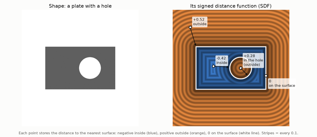
SDF (Signed Distance Function) is a function that returns, for any point in space, how far that point is from the surface of a solid. The distance has a sign: negative inside the solid, positive outside it, and 0 exactly on the surface.
Representing a solid with an SDF has several advantages.
- Any shape can be represented in the same way. Flat surfaces, curved surfaces, holes, and recesses can all be expressed using a single kind of information: distance values.
- It is well suited to AI output. The AI only needs to learn a function that returns a distance when given the coordinates of a point, without having to deal with issues such as different numbers of vertices for different shapes.
- It can be converted to polygons at any time. Extracting the surface where SDF = 0 produces a 3D model.
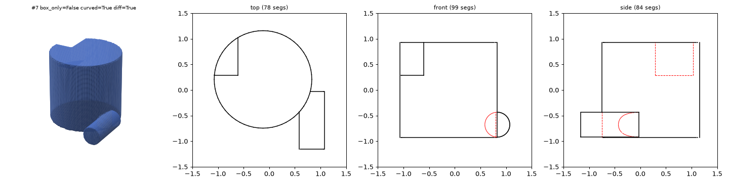
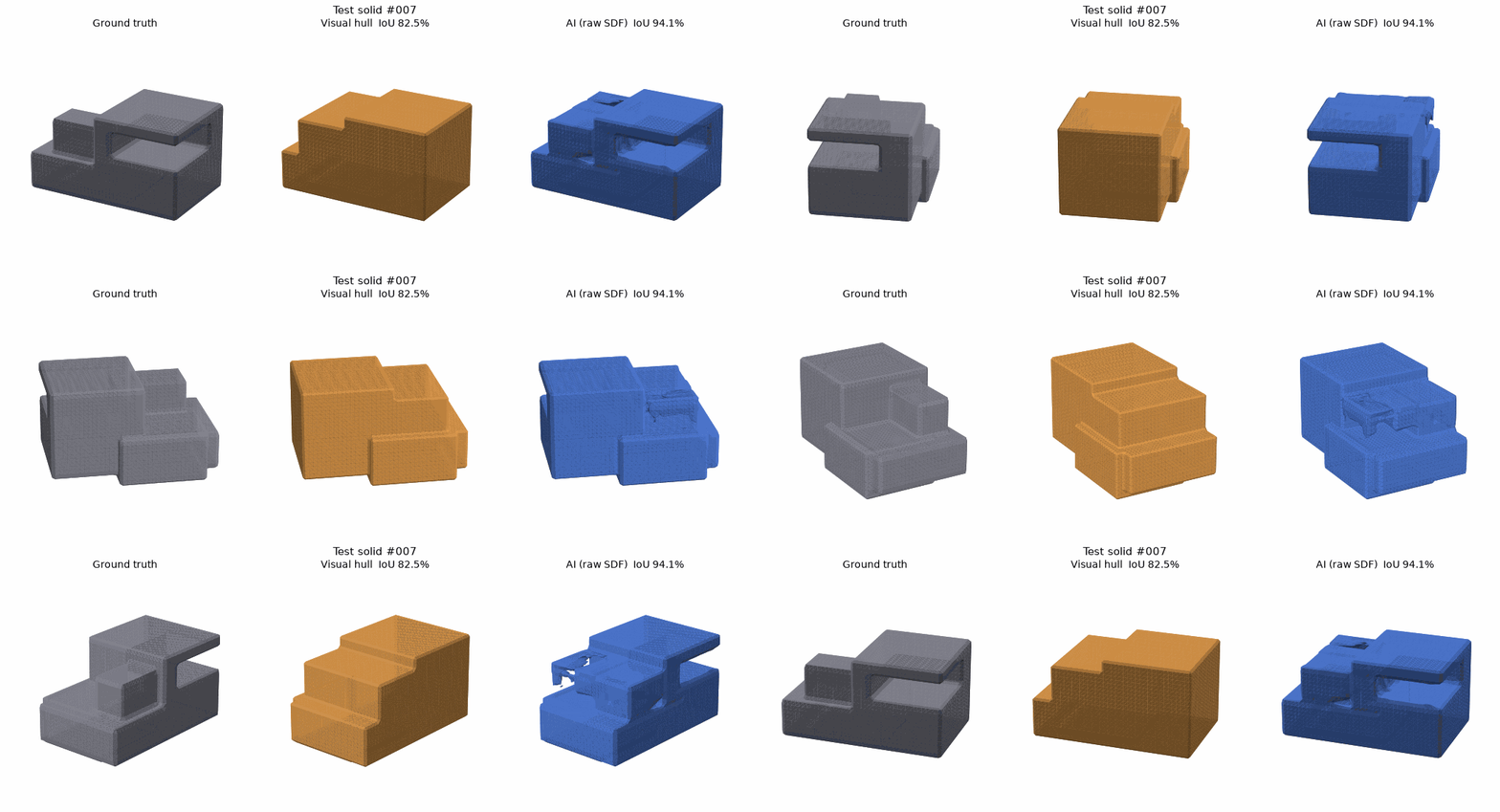
There are also weaknesses. An SDF learned by AI tends to make corners and narrow grooves slightly rounded and blurred. Even in the right side of Figure 1, an extra line appears inside the semicircular notch. For this reason, this project uses the SDF not as the final shape, but as a rough guide or “draft” of the shape.
How It Works
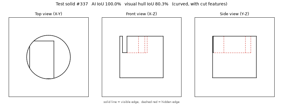
- The input consists of three orthographic views drawn with solid lines for visible edges and dashed lines for hidden edges. The lines are provided not as images, but as lists of coordinates.
- For each point in space, the AI examines where that point lies relative to the lines in each view—for example, which lines are nearby and how many lines are crossed in each direction—and estimates the SDF value.
- The SDF is used to capture the overall shape (Stage 1).
- Exact coordinates are taken from the drawings, while the SDF is used to decide which ones should be selected, and an accurate polygon model is then constructed (Stage 2).
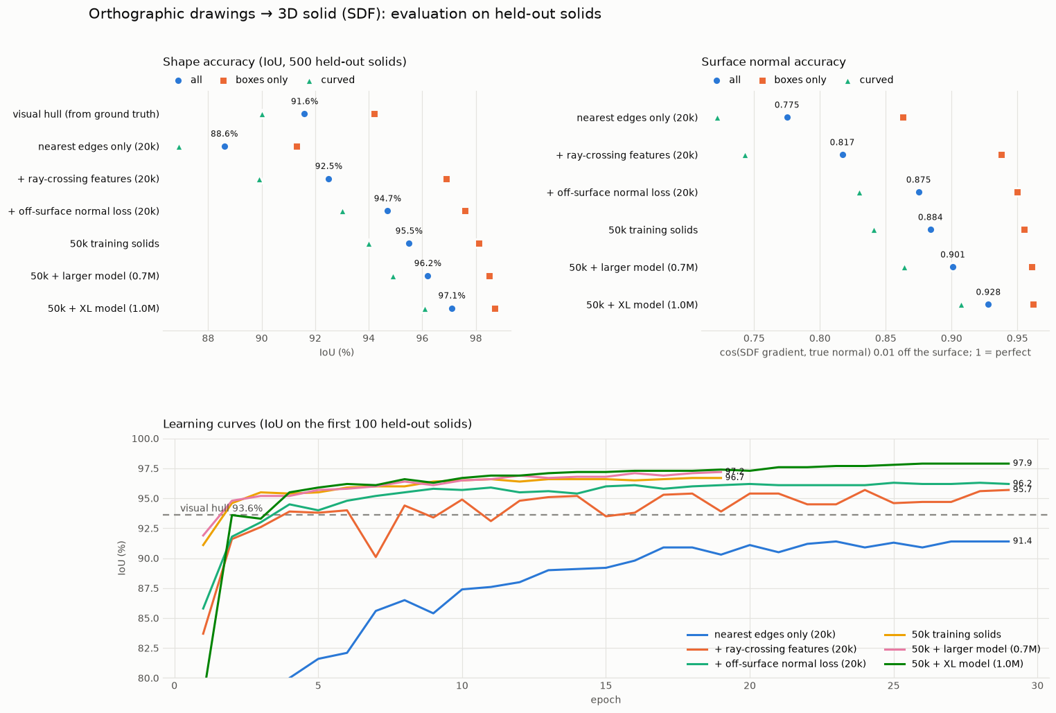
The training data consists of solids created by randomly adding and subtracting rectangular boxes, cylinders, spheres, and tori, along with their corresponding orthographic drawings. Because the solid is created first and the drawings are generated from it, the correct answer (Ground Truth, or GT) is known exactly. We use 50,000 samples for training and evaluate the system on 500 samples that were never used for training.
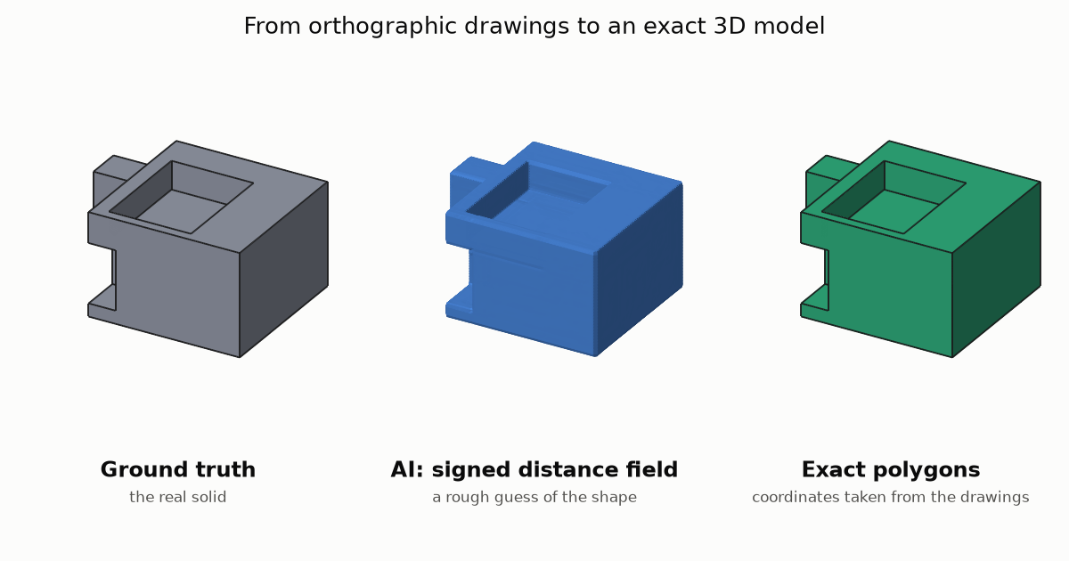
As a comparison baseline, we also calculate the Visual Hull. This is a solid created by using only the silhouettes from the three orthographic views, extruding the projections from three directions, and intersecting them. It represents the performance of an approach that relies only on the outer contours, so the amount by which the AI exceeds it can be interpreted as how much information the AI has learned to read from the interior of the drawings, such as hidden dashed lines.
What We Have Achieved So Far
Shape Estimation: 97.1% IoU Across 500 Test Samples
The average IoU—the overlap ratio between the prediction and the ground truth—was 97.1% across the 500 test samples. For combinations of rectangular boxes, the IoU was 98.7%, while shapes containing curved surfaces achieved 96.1%. The corresponding Visual Hull scores were 91.6%, 94.2%, and 90.0%, respectively, so the AI outperformed the baseline in every category.
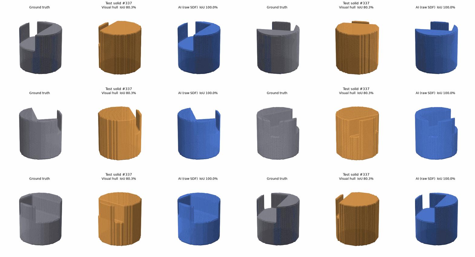
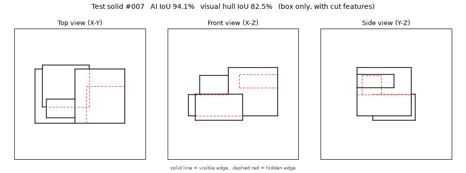
Let us look at some actual examples. From left to right, the images show the ground truth, the Visual Hull, and the AI output—the SDF converted directly into polygons.
Accurate Polygonization: 72.5% Exact Matches for Box-Based Shapes
We also tested a process for constructing an accurate 3D model using the SDF as a rough guide. For combinations of rectangular boxes, this can be done with the following procedure.
- Collect the x, y, and z coordinate values directly from the endpoints of lines in the orthographic drawings, using the drawing values exactly as they are.
- Divide the space into small rectangular cells using those coordinates.
- Use the SDF to determine whether each cell is “solid” or “empty.”
- Connect the outer faces of the solid cells to create polygons.
- Regenerate the three orthographic views from the resulting solid and verify whether they match the input drawings.
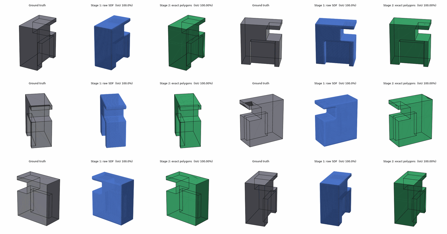
The final verification step is especially important. Every shape that passed verification (56.6%) matched the correct answer without exception. In other words, even without knowing the ground truth, it is possible to use the drawings alone to confirm that “this result is correct.” On the other hand, some shapes that failed verification were actually correct but were judged as mismatches because of small differences in how the drawings were rendered (15.9%), so the verification criteria still need further adjustment.
Future Directions and Limitations
Future directions
- Performance is still improving steadily as the dataset and model become larger. The gains are particularly strong for curved surfaces.
- Instead of breaking curves into small line segments, passing arcs directly to the AI is expected to reduce blurring on curved surfaces.
- For shapes containing curves, it should be possible to read dimensions from circles in the drawings and construct accurate models using CAD software components such as OpenCascade.
- Supporting four or more views and sectional drawings should make hidden-shape estimation even more accurate.
Limitations
- Difference from real-world drawings: At present, the model has only been trained on “clean drawings” that we generated ourselves. We have not yet tested it on actual engineering drawings containing dimension lines, annotations, or abbreviated notation.
- Drawings with more than one possible answer: Different solids can sometimes produce exactly the same three orthographic views, making it impossible in principle to determine a single correct answer. A system that presents multiple candidates for a human to choose from will be necessary.
- A tendency to fill uncertain regions: When the model is unsure, it tends to answer “solid,” which can cause hidden recesses to be filled in (Figure 7).
- Limits on fine detail: Very narrow grooves or thin walls relative to the size of the part are difficult to represent accurately.
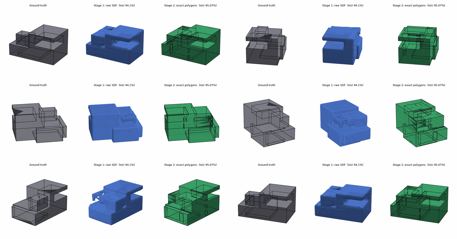
An SDF alone cannot produce dimensionally exact CAD. However, it has reached fairly high accuracy as a rough guide to the shape, and the results suggest that combining it with exact coordinates taken from drawings can produce completely correct 3D models.
Conclusion
An SDF by itself cannot become dimensionally exact CAD data.
Corners become slightly rounded, and narrow grooves become blurred.
Even so, as a rough guide to “where material exists and where space is empty,” it achieved more than 97% accuracy on shapes that were never used for training.
We also confirmed that it can read hidden recesses from dashed lines in the drawings and cut them out—something that cannot be inferred from the outer silhouette alone.
We also learned that there is no need to leave everything to the SDF.
Dimensions can be taken accurately from the drawings, while the AI is responsible only for deciding “which ones to use.”
Finally, the resulting solid can be used to regenerate the three orthographic views and check whether they match the input.
With this combination, for shapes composed of rectangular boxes, we can now automatically construct 3D models that exactly match the correct answer, including verification that the result is correct.
The biggest takeaway from this experiment is that a useful division of roles is beginning to emerge: the AI provides a “fuzzy understanding,” while rule-based processing provides “precise calculation and verification,” allowing each approach to compensate for the other's weaknesses.
Struggling to turn ideas into reality? With a proven track record of over 1,000 clients, our agile and flexible team will accelerate your business growth.