DIY Conveyor Automatic Capture Machine for AI Datasets
Abstract
At Vitalify Asia, we are a web & mobile app development company. We provide rapid product development and improvement on the DevOps basis with the team committed to providing value to users.
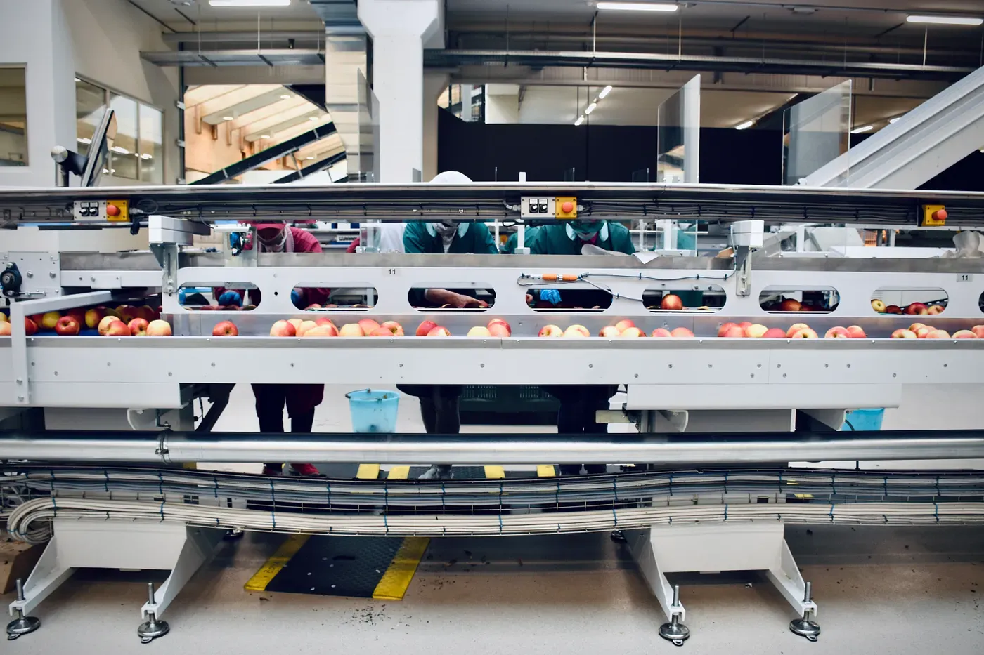
Inspection in production is a very important process, currently, technologies are often applied based on OpenCV and algorithms to perform, this process is needed to improve performance as well as classification ability. Therefore, the application of deep learning in the process is extremely important, but experiments need to be built from the Lab to ensure feasibility if needed. We conduct this experiment as a way of simulating the actual conveyor to collect data for training the deep learning model, also we can use it as the quality control in case a bad product will be alert when it ran on the conveyor.
Introduction
Implemented conveyor modeling to test automatic data collection during production, which is not easy to do in practice due to the constraints of production conditions. After building the conveyor model, we proceed to collect specimen images, train the deep learning model and evaluate the results.
Build conveyor
Made with the following idea: the item will be placed on the conveyor, the conveyor moves at a preset speed, when the item is detected in the given area, stops the conveyor, activates the camera, takes a photo and continues for the next item
Ingredients needed to proceed:
- Arduino, motion control conveyor, object detection, photography
- Breadboard and Jump Wires
- The material for making conveyor
- Sensor HC-SR04
- Camera, connect to Arduino to take pictures when item is detected
System schema
Connecting together
Step Motor and Arduino
To control step motor with Arduino, we need to use the drive in Full Step Mode. It means we need to send 200 pulses into the Step Pin to make one full cycle rotation, so we will leave the 3 pins disconnected and just connect the Direction and the Step pins of the drive to the pins number 3 and 4 on the Arduino Board and as well the Ground and the 5V pins for powering the board. Also we will use a 100µF capacitor for decoupling and 12V, 1.5A adapter for powering the motor. We will use a NEMA 17 bipolar Stepper Motor and its wires A and C will be connected to the pins 1A and 1B and the B and D wires to the 2A and 2B pins.
One thing need to be considered that is we need to stop the step motor immediately when the object coming. If we use full circle rotation mode, the motor is still turn a little bit to finish its rotation. Therefore, we will reduce the cycle rotation as much as it can. In this case, step motor NEMA 17 can perform 1/16 of a full cycle rotation.
Sensor SRF04 and Arduino
The HC-SRF04 Module has 4 pins, Ground, VCC, Trig and Echo. The Ground and the VCC pins of the module needs to be connected to the Ground and the 5 volts pins on the Arduino Board respectively and the trig and echo pins to any Digital I/O pin on the Arduino Board.
In order to generate the ultrasound we need to set the Trig on a High State for 10 µs. That will send out an 8 cycle sonic burst which will travel at the speed sound and it will be received in the Echo pin. The Echo pin will output the time in microseconds the sound wave traveled.
So, when setting up this sensor on the Conveyor Belt, we need to compute the width of conveyor, called ⍺, then if the distance of detected object and the sensor is less than ⍺, it means that is the right time to active the camera for taking photos.
Camera and Arduino
When the RIGHT, LEFT and GND pins is connected together, the shooter of camera will be activated. We use 2 optos PC817 as triggers to join these ins into as one. Specifically, the first 1kΩ resistor is connected between pin 2 on the Arduino board and the positive side of the optocouplers led in the chip, this resistor cuts down the voltage from the board so it does not overpower the led and burn it out. Similarly, the second 1kΩ resistor is also connected to the second opto. The idea is that we set pin 2 and 3 to 5V, then the brighter inside opto will allow to pass through the phototransistor. Based on this theory, we will it to capture photos.
Some videos of the conveyor
For more details, can refer my source code: https://github.com/chnghia/conveyor-belt
Some projects using the conveyor
Here are some projects done with this conveyor.
- Project on detecting errors in candy production
- Project on detecting errors of car logos
Conclusion
Conveyor stop handling and object capture can be applied as input for real-world testing, then when an error is detected, an object will be alerted and ejected from the conveyor.
In case working on a similar project, here is some considering points:
- The speed of the conveyor will affect the image quality, this should be kept in mind when implementing on a real system, because the actual conveyor is often high speed.
- Shooting speed of the camera, mobile phone camera is used in the experiment, but when deployed, it needs to require a camera with a higher shooting speed.
References
- Images from — “https://howtomechatronics.com”
The company
Our company is involved in a wide range of projects, not only AI development, but also mobile/web application development. We would be happy to discuss your needs with you.
Struggling to turn ideas into reality? With a proven track record of over 1,000 clients, our agile and flexible team will accelerate your business growth.
Book a Free ConsultationMore on "Web & Cloud Infra"

Part 1: Introduction to gRPC Framework
gRPC is a robust open-source RPC framework used to build scalable and fast APIs for modern applications.

End-To-End Encryption (E2EE): A First Glance
A billion messages and video calls are made daily. Learn how End-To-End encryption (E2EE) keeps them secure.

Podman Desktop: A Docker Alternative for Developers
Podman is an open-source container management engine. Discover why it's a popular alternative to Docker.